My own EWI
This is a classic example of “taking an exit ramp” from a project. I wanted to make my own version of an electric wind instrument (EWI) but also wanted to involve my friends in a fun group project.
The Idea
The Akai EWI is a really cool. A novel method of MIDI interface with a computer, that makes you play differently than if you were playing on a keyboard. I don’t know how to play saxophone, so I also think this would be a novel approach to music. Sure, you can buy one for $900, but that’s stupid. Its fairly common practice for internet weirdos to make their own ones.
Prior art
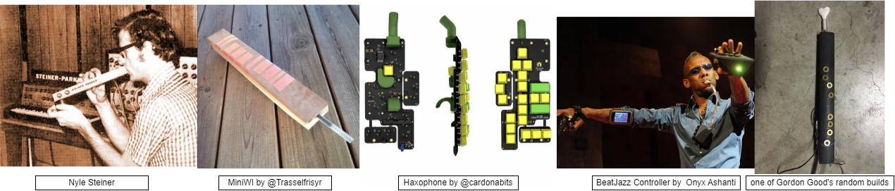
Had to give a search for some classic, non-product, EWI constructions.
- The guy who invented the EWI Nyle Steiner has his own page of novel instruments.
- MiniWI by @Trasselfrisyr is a classic minimum viable product, simple construction with conductive copper pads.
- Haxophone by @cardonabits is a good modern design with mechanical keyboard switches. Also uses fluidsynth.
- BeatJazz Controller by Onyx Ashanti has a radically different form factor. He uses PureData for non-ADSR synthesis and processing of the raw input data.
- Gordon Good has been in the game for years, and also fun fact does projects at CCRMA at Stanford. Has a bunch of blog posts about non-ADSR synthesizers.
- There were also several builds at Opensauce 2025 that were generally similar to these builds.
Our Build
First we have to talk about who the team was. I gathered a few friends; Harry, Ian, and Brooke. The first consideration we wanted to make was who the device was for. Each of us wanted to play one, and knew maybe 1 or 2 other people who might find them interesting if they worked.
This led to a batch size of maybe 3-6 devices, which is a weird number. Its low enough that custom PCBs are still annoying and expensive, and any annoying processes in the construction steps would have to be somewhat repeatable. We also had no delusions that we would be making any money off this, so using like a $200/ea bite force sensor would probably not be a worthwhile inclusion. Goal was cheap, repeatable, and functional enough.
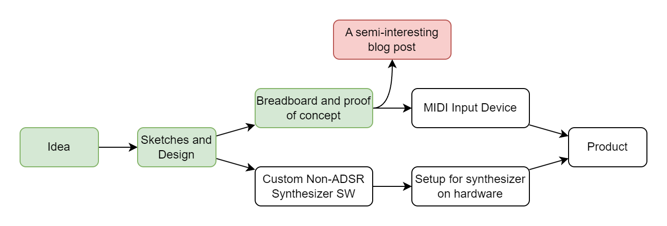
The gang went back and forth but we ultimately decided to separate the input management from the synthesizer part - use an arduino with its many input channels on one side of the versatile MIDI interface, and then connect it to anything downstream, a full computer or some embedded synthesizer. This also gave us a few off ramps to consider.
We also decided that using capacitive pads would be simpler to wire and easier/faster to play, so we decided to look into soldering to pads or tape or something. This would result in a less tactile device, which could be a downside, but that was deemed an acceptable tradeoff.
Side note: Off Ramps
Sometimes you realize you are done working on a project. Not that the project is complete, but that the remaining work is not novel or compelling. This is where the “off ramp” comes into play - a point where the project is presentable and demonstrates something interesting, even if the full vision is not complete. As my projects grow in scale, I find it more useful to build these points in from the very design and planning phase. I also want to note that this doesn’t make me any less motivated to go through and finish a project - it maybe makes it even easier to approach large goals, because I know failure will still leave me with something.
I want to credit this idea and phrasing to Brooke, who really demonstrated it with her quilted jacket project. Link will be added here if she ever posts about it.
Build - Part 2
Parts List
This is for the MIDI instrument part. The synth part would be connected over USB to this component.
| Part | Count | Price/per |
|---|---|---|
| Arduino Pro Micro | 1 | ~$5 |
| 3.3-5V logic level shifter | 1 | ~$1 |
| MPR121 Capacitive touch breakout board | 2 | ~$3 |
| TM7711 ADC + Pressure Sensor | 2 | ~$2 |
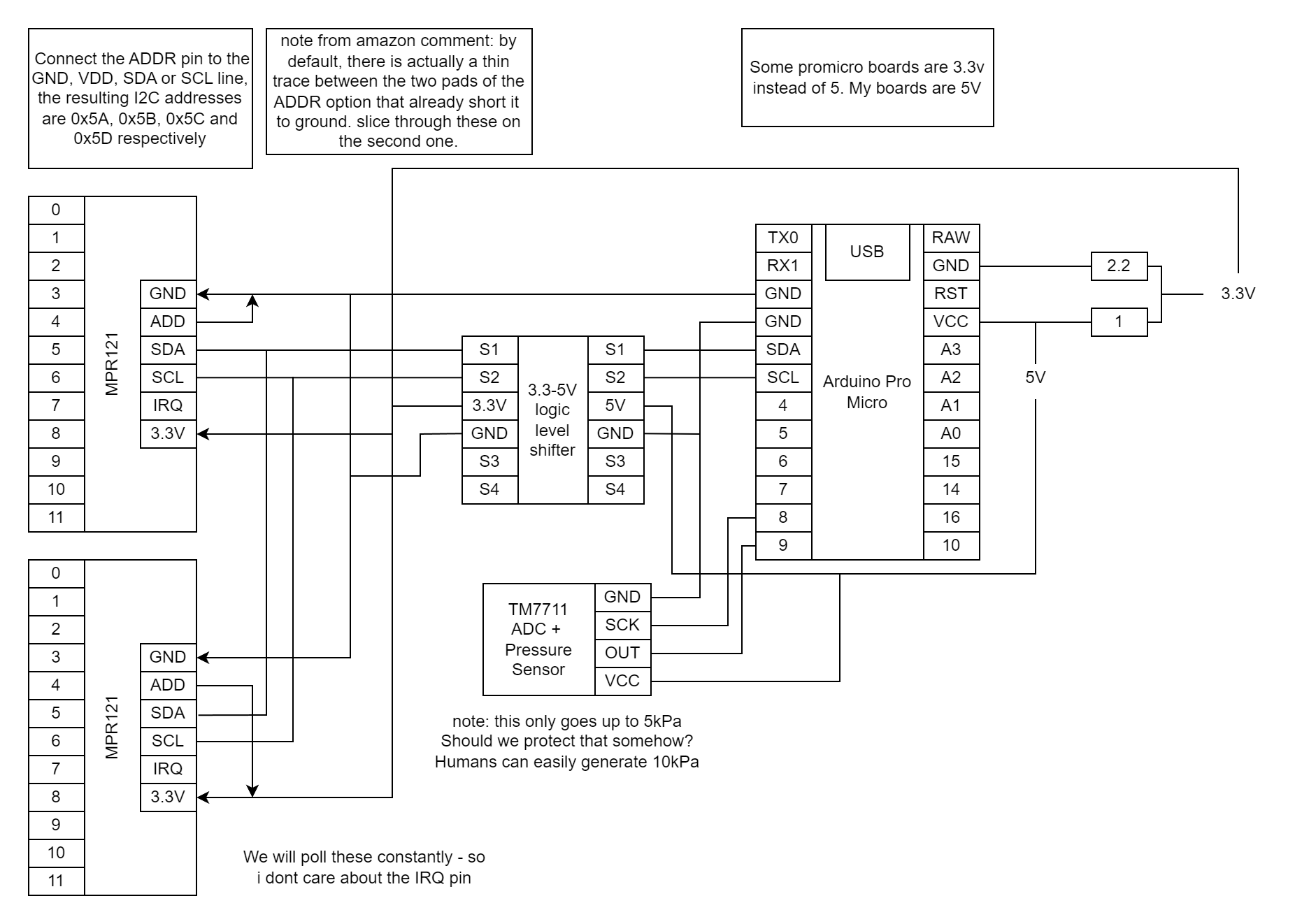
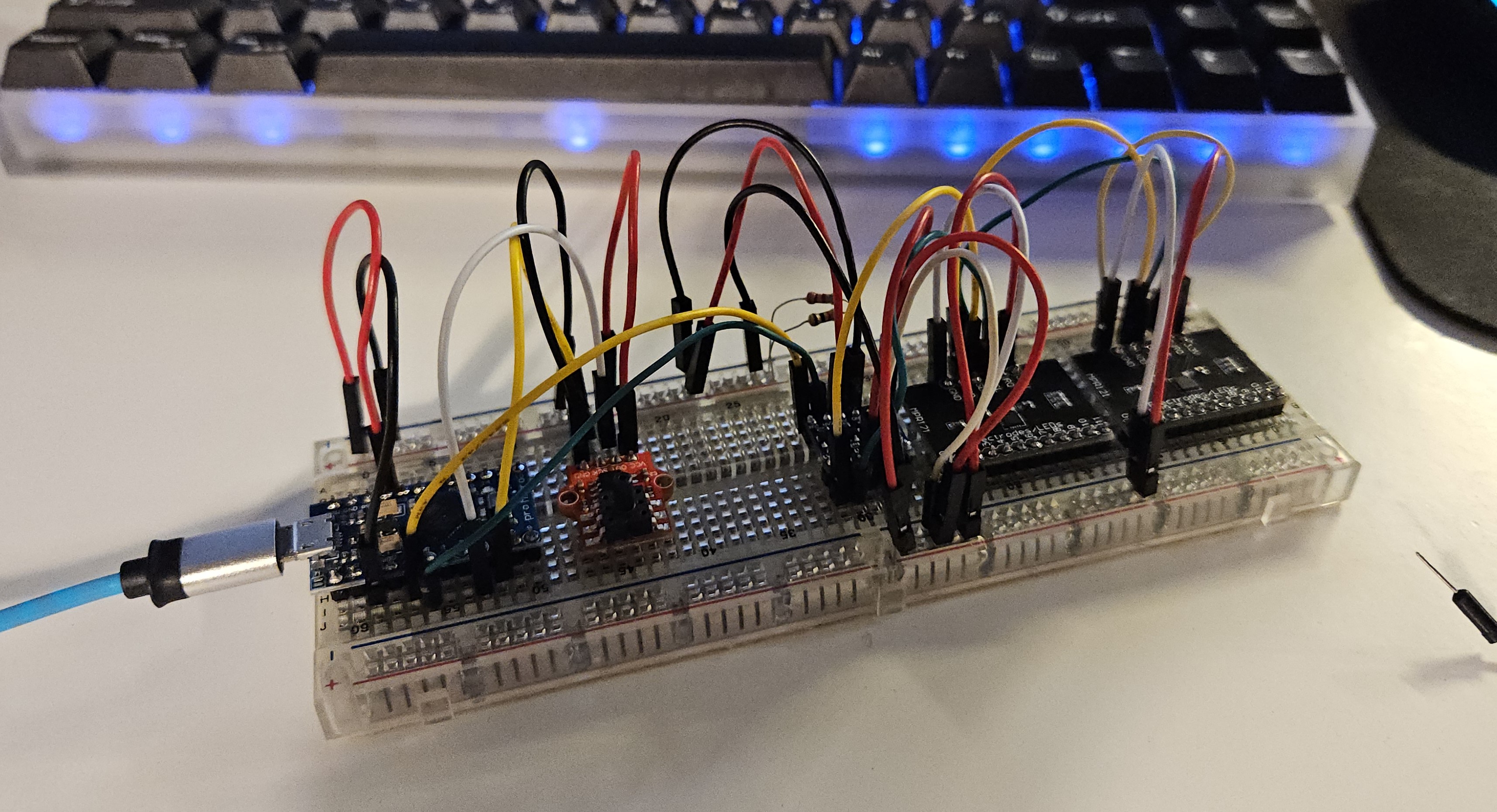
I got all the parts a few weeks later, and started breadboarding them together. Simple circuits with the example code to get things working. Around here I think I accidentally broke one of the breath sensors, either by blowing too hard or maybe soldering it too hot. Not sure, I just kind of expect those things to have a failure rate. There is a flexible diaphram in there somewhere, and I think its possible for a human to overpower it.
Software Design
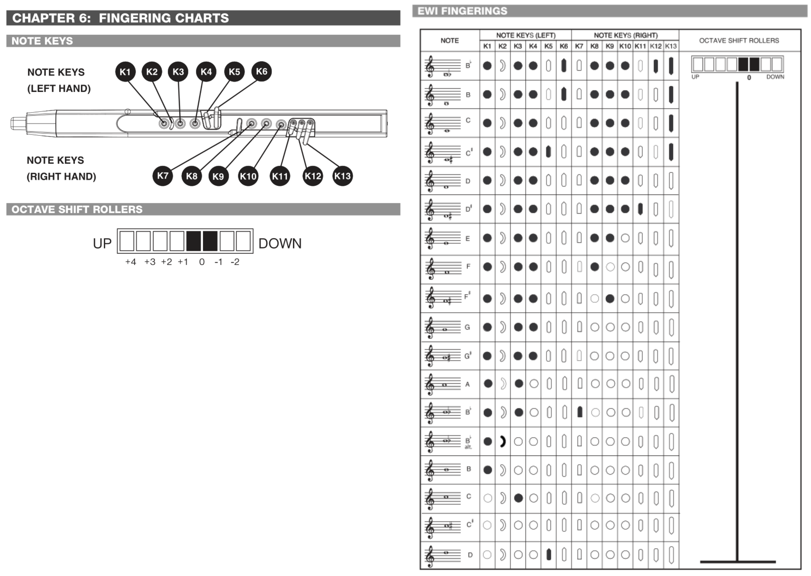
As I said, I don’t know how to play any woodwind instruments. I decided that the engineers at Akai probably know a thing or two about how to map keys to notes - and great engineers steal.
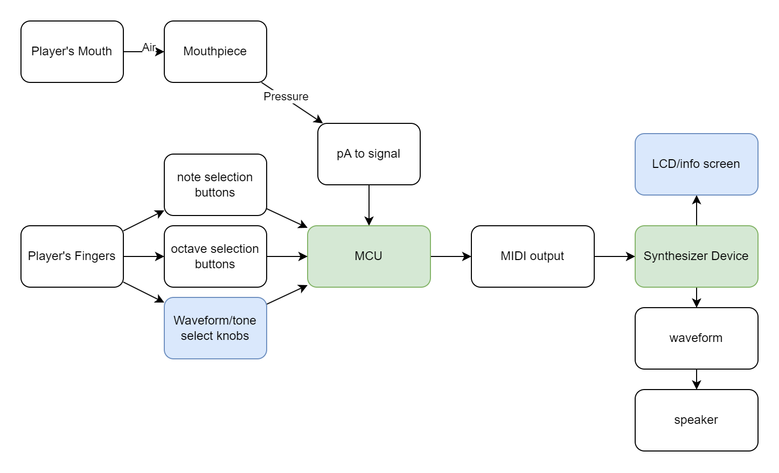
I then just made sure I had enough IO channels to match the button setup.
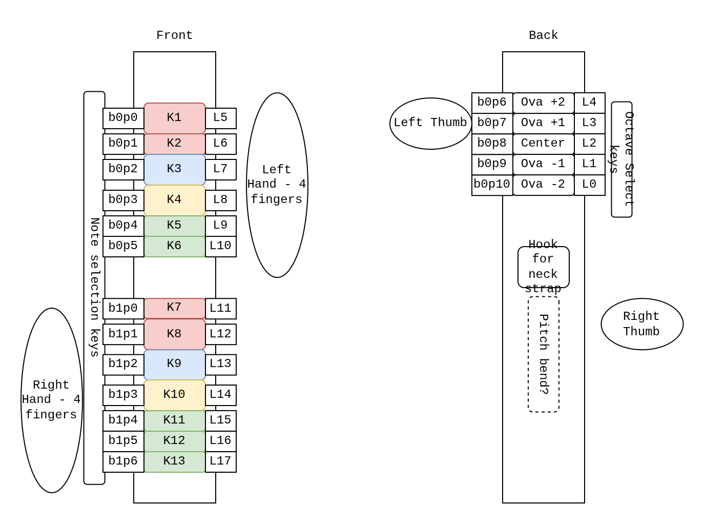
This diagram outlines multiple useful values for me to keep track of.
- Most prominent is a number prefaced with a
K. This maps them to keys in Akai’s manual. - the number in the pattern
bxpxis the IO board index and channel index. There are two boards with 12 channels each. - the number prefaced with an
Lindicates where in the flat array of booleans I place that value.
I wanted to use this project to practice some boolean operators. This was mostly just for love of the game. Here is an array I used to mask input values and translate them into the right spot in the array. During testing I noticed that the first two pins on one of my capacitive boards weren’t working, so I just rewired it on the spot and kept the naming the same (if you are trying this project out yourself, I hope you notice and change this if your boards work properly).
// define input to keys
// this should match the wiring you make.
uint32_t io_keys_map[NUM_IO] = {
    // board 0
    0b000000000000000000,
    0b000000000000000000, //p0 // the first two pins are broken?
    0b000000000000100000, //p1
    0b000000000001000000, //p2
    0b000000000010000000, //p3
    0b000000000100000000, //p4
    0b000000001000000000, //p5
    0b000000010000000000, //p6
    0b000000000000010000, //p7
    0b000000000000001000, //p8
    0b000000000000000100, //p9
    0b000000000000000010, //p10
    0b000000000000000001, //p11
    0b000000000000000000, //x12 unused
    0b000000000000000000, //x13
    0b000000000000000000, //x14
    // board 1
    0b000000100000000000, //p0
    0b000001000000000000, //p1
    0b000010000000000000, //p2
    0b000100000000000000, //p3
    0b001000000000000000, //p4
    0b010000000000000000, //p5
    0b100000000000000000, //p6
    0b000000000000000000, //p7 unused
    0b000000000000000000, //p8
    0b000000000000000000, //p9
    0b000000000000000000, //p10
    0b000000000000000000, //p11
    0b000000000000000000, //x12
    0b000000000000000000, //x13
    0b000000000000000000, //x14
    0b000000000000000000  //x15
  };
All you need to do to start with an array of physical “buttons” and create an array of “keys” is to AND and then ADD the bitmasks.
// read from inputs
touched_b0 = b0.touched();
touched_b1 = b1.touched();

// turn into logical values
m_allbuttons_held = touched_b0 + ((uint32_t) touched_b1 << 16);

m_allkeys_held = 0;

// map the IO to the keys in order
for (int i=0; i<NUM_IO; i++) {
  testbit = (uint32_t) 1 << i;
  if (m_allbuttons_held & testbit) {
    m_allkeys_held += io_keys_map[i];
  }
}
Then I just copied from the manual to make the fingerings.
// define EWI fingerings
// write in binary which buttons are pressed and associate with a note.
const uint8_t NUM_FINGERINGS = 18;
int32_t keys_notes_map[NUM_FINGERINGS][2] = {
    {0b1011010111011, pitchB2b},
    {0b1011010111001, pitchB2},
    {0b1011000111001, pitchC3},
    {0b1011100111001, pitchD3b},
    {0b1011000111000, pitchD3},
    {0b1011000111100, pitchE3b},
    {0b1011000110000, pitchE3},
    {0b1011000100000, pitchF3},
    {0b1011000010000, pitchG3b},
    {0b1011000000000, pitchG3},
    {0b1011100000000, pitchA3b},
    {0b1010000000000, pitchA3},
    {0b1010001000000, pitchB3b},
    {0b1100000000000, pitchB3b},
    {0b1000000000000, pitchB3},
    {0b0010000000000, pitchC4},
    {0b0000000000000, pitchD4b},
    {0b0000100000000, pitchD4}};
As you can see, there are invalid fingerings, that could be possibly triggered while transitioning between notes. I just hold the last note, but it would be interesting to get into semitone world. That would be a whole different model though.
int16_t getNote(uint32_t keys_held)
{
  for (uint8_t i = 0; i < NUM_FINGERINGS; i++)
  {
    if (keys_held == (uint32_t) keys_notes_map[i][0])
    {
      return keys_notes_map[i][1];
    }
  }
  return m_last_valid_note;
}
From here, I had the breath cause both a NOTEON/NOTEOFF effect when it crossed a threshold, as well as mapping to two different CC channels. One for positive pressure and another for negative pressure. The pitches are sent every cycle that NOTEON is active.
Whats Next
I have like zero desire to build or design the rest of this thing, so I just finished the breadboard test. I don’t think this project is particularly groundbreaking in the world of electronic breath synthesizers, so only if other members of the team pick up the effort will I continue.